Adobe's Lightroom is really great. I now use LR for my 97% of time processing and printing photos. (The remaining 2% time uses Photoshop and 1% uses Silverfast).
However, LR is limited on color management and many times it causes annoying inconvenience:
(1) No soft proofing in LR's print module. For critical printing work, one has to open the file in Photoshop for soft proofing. My 16-bit color images scanned from 8x10 film are 1.5 GB and opening them in both LR and PS can be really slow, if not crashing my computer.
(2) The rendering color profile used in LR's Develop module is ProPhoto RGB but in Library and Print module it is Adobe RGB (1998). Because of this, I have seen some color inconsistency when the image is seen at different LR modules. For example, some deep reds cannot be shown in Adobe RGB color space.
I guess Adobe does not want LR to reduce too much users from PS so they purposely make the LR imperfect... sigh.
Thursday, December 9, 2010
Friday, August 20, 2010
A Zemax Case
I had a design using a prism pair to circularize laser diode's elliptical beam. The theoretical plot is below:

The prism positions are designed for 488nm, wavelengths deviating from 488nm will have some beam walk-off (both displacement and steering). Now I want to know how much I need to twist the prism pair for correcting the beam walk-off. The pivot point of twisting is a pin at somewhere not far from the prisms. (Twist the two prisms together since this is a sub-assembly).
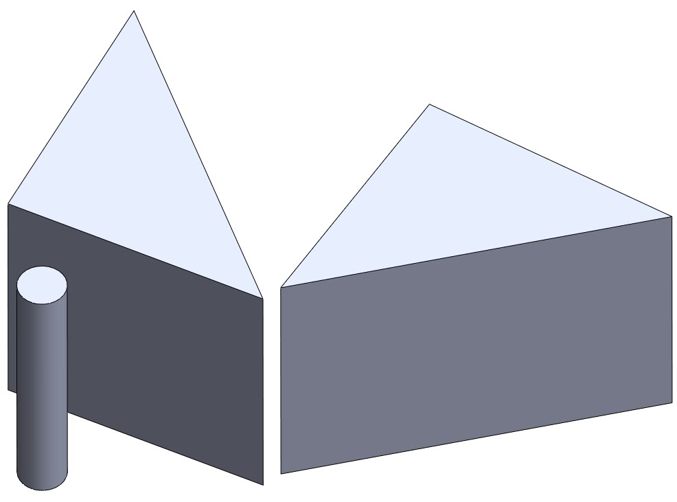
To simulate it in Zemax, I first draw the prisms in SolidWorks with the pivot pin:

Note that in SolidWorks I make the origin point at the pin location. Then I Save As the model in IGS format, to folder C:\Program Files\ZEMAX\Objects\CAD Files. After Zemax imports this file, the reference point is at the pin, which is what I wanted. I found that saving as STL file won't keep the reference point at the same location as in SolidWorks.
Below is the Zemax screen capture. It is a non-sequential model. I can rotate two prisms together around the pin location in Zemax. Beam compression, displacement and steering can all be checked. (Click on images to see in full size.)


The prism positions are designed for 488nm, wavelengths deviating from 488nm will have some beam walk-off (both displacement and steering). Now I want to know how much I need to twist the prism pair for correcting the beam walk-off. The pivot point of twisting is a pin at somewhere not far from the prisms. (Twist the two prisms together since this is a sub-assembly).
To simulate it in Zemax, I first draw the prisms in SolidWorks with the pivot pin:
Note that in SolidWorks I make the origin point at the pin location. Then I Save As the model in IGS format, to folder C:\Program Files\ZEMAX\Objects\CAD Files. After Zemax imports this file, the reference point is at the pin, which is what I wanted. I found that saving as STL file won't keep the reference point at the same location as in SolidWorks.
Below is the Zemax screen capture. It is a non-sequential model. I can rotate two prisms together around the pin location in Zemax. Beam compression, displacement and steering can all be checked. (Click on images to see in full size.)


Monday, January 25, 2010
Basic of basics of polarization and reflection.
Once upon a time these were taught in college; but I need to refresh them in my mind every once in a while.
p and s polarization: (forget about their Greek/German/? equivalent) Here p means "plunge", s means "stick". Because p light is easier to penetrate (plunge into water) whereas s light is easier to be reflected (a stick bounced from water).
At Brewster angle, the reflected beam is purely s-polarized, meaning the p-polarized light has zero reflectance. Wikipedia [1] has an excellent image to show this effect:

Reflectance vs incident angle is below (for 532nm and fused silica):

At Brewster angle (~56o), reflectance of s-polarization is about 14%.
References and notes
[1] http://en.wikipedia.org/wiki/Polarizer
Wednesday, August 12, 2009
Using Zemax as a calculator to calculate for Gaussian beam
Using Zemax to calculate for Gaussian beam propagation is handy and precise.
First set up your optical system in sequential mode. For example, a lens comprised of two surfaces. Here I have a diode window and a collimating lens:

Go to Analysis -> Physical Optics -> Paraxial Gaussian Beam, or simply Ctrl-B. A "Paraxial Gaussian Beam Data" window appears. Click Settings, or right click mouse, the setting menu appears.
Zemax asks for 4 initial values to define the input Gaussian beam:
(1)Wavelength: defined in "Wav" tab.
(2)Waist size: this is 1/e2 radius value. Note that this is for the embedded ideal Gaussian beam.Note 1
(3)M2 factor: the true Gaussian beam has Mx beam radius and Mx divergence compared to the embedded ideal Gaussian beam.
(4)Waist location.

After hitting OK, the "Paraxial Gaussian Beam Data" window gives Gaussian beam characteristics on all surfacesNote 2. Both embedded and true Gaussian modes will be given. This is better than calculating by hand or by Matlab code that I used to do.
What would be better: I wish Zemax can creat a drawing showing Gaussian beam's marginal ray.
Notes:
1. To convert your real beam's waist size to its embedded Gaussian beam's waist, divided it by M.
2. This is ideal paraxial result without considering any aberrations on the optics. To see how aberration changes the Gaussian beam size, use "Skew Gaussian Beam" function.
First set up your optical system in sequential mode. For example, a lens comprised of two surfaces. Here I have a diode window and a collimating lens:
Go to Analysis -> Physical Optics -> Paraxial Gaussian Beam, or simply Ctrl-B. A "Paraxial Gaussian Beam Data" window appears. Click Settings, or right click mouse, the setting menu appears.
Zemax asks for 4 initial values to define the input Gaussian beam:
(1)Wavelength: defined in "Wav" tab.
(2)Waist size: this is 1/e2 radius value. Note that this is for the embedded ideal Gaussian beam.Note 1
(3)M2 factor: the true Gaussian beam has Mx beam radius and Mx divergence compared to the embedded ideal Gaussian beam.
(4)Waist location.
After hitting OK, the "Paraxial Gaussian Beam Data" window gives Gaussian beam characteristics on all surfacesNote 2. Both embedded and true Gaussian modes will be given. This is better than calculating by hand or by Matlab code that I used to do.
What would be better: I wish Zemax can creat a drawing showing Gaussian beam's marginal ray.
Notes:
1. To convert your real beam's waist size to its embedded Gaussian beam's waist, divided it by M.
2. This is ideal paraxial result without considering any aberrations on the optics. To see how aberration changes the Gaussian beam size, use "Skew Gaussian Beam" function.
Wednesday, June 24, 2009
Abbe number and glass code

Abbe number:
| V = | nD - 1 nF-nC | (1) |
where nD, nF and nC are the refractive indices of the material at the wavelengths of the Fraunhofer D-, F- and C- spectral lines (589.2 nm, 486.1 nm and 656.3 nm respectively). Low dispersion (low chromatic aberration) materials have high values of V [1].
Glass code:
Example of BK7:
517642
n = 1.517
V = 64.2
(both at 587.56 nm) [2]
References:
[1] http://en.wikipedia.org/wiki/Abbe_number
[2] http://en.wikipedia.org/wiki/Glass_code
ZEMAX un-organized tips
I have to do extensive ZEMAX work to start my semi-new job. Had some non-sequential mode experience but now I really have to use sequential mode, and optimization and tolerancing functions. The first two tasks are aspheric collimating lens for diode and fiber-coupling. Now let me start to accumulate the little rules/tips of ZEMAX:
1. When defining a sequential system, the first parameter to set is aperture. Some aperture types are:
a. Float by stop size: defined by the radius of the stop surface. This type of aperture is used when the stop surface is a real, unchangeable aperture buried in the system, for example, fiber coupling.
b. Object cone angle: defined by the half-angle in degrees of the marginal ray in object space. This can be used when designing a collimating lens for a diode laser.
(Ref[1], page 63)
2. Afocal system [2]. The strict definition of an afocal system is a system in which both object and image conjugates are at infinity. For example, a laser beam expander in which both input and output beams are collimated. In Zemax, as long as the image conjugate is at infinity, the system is afocal. For example, when designing a diode collimating lens, one will choose "Afocal image space" in Aperture settings:

3. Apodization type. This describes amplitude variation of the pupil illumination. Gaussian apodization is what a laserist often uses:
Here ρ is the normalized pupil coordinate, i.e., ρ = 0~1 from the center to the edge of the pupil. G is the apodization factor. If G = 1, the amplitude at the edge of the entrance pupil falls to 1/e of the center value (intensity falls to 1/e2). So the marginal ray represents the 1/e2 ray.
(Ref[1] page 64)
Marginal ray: is the ray that travels from the center of the object, to the edge of the entrance pupil, and onto the image plane.
(Ref[1] page 30)
References:
[1] ZEMAX user's guide Jan 2003
[2] Mark Nicholson, ZEMAX users' knowledge base - How to design afocal systems. http://www.zemax.com/kb/articles/36/1/How-to-Design-Afocal-Systems/Page1.html
1. When defining a sequential system, the first parameter to set is aperture. Some aperture types are:
a. Float by stop size: defined by the radius of the stop surface. This type of aperture is used when the stop surface is a real, unchangeable aperture buried in the system, for example, fiber coupling.
b. Object cone angle: defined by the half-angle in degrees of the marginal ray in object space. This can be used when designing a collimating lens for a diode laser.
(Ref[1], page 63)
2. Afocal system [2]. The strict definition of an afocal system is a system in which both object and image conjugates are at infinity. For example, a laser beam expander in which both input and output beams are collimated. In Zemax, as long as the image conjugate is at infinity, the system is afocal. For example, when designing a diode collimating lens, one will choose "Afocal image space" in Aperture settings:
3. Apodization type. This describes amplitude variation of the pupil illumination. Gaussian apodization is what a laserist often uses:
| A(ρ) = exp(-Gρ2) |
Here ρ is the normalized pupil coordinate, i.e., ρ = 0~1 from the center to the edge of the pupil. G is the apodization factor. If G = 1, the amplitude at the edge of the entrance pupil falls to 1/e of the center value (intensity falls to 1/e2). So the marginal ray represents the 1/e2 ray.
(Ref[1] page 64)
Marginal ray: is the ray that travels from the center of the object, to the edge of the entrance pupil, and onto the image plane.
(Ref[1] page 30)
References:
[1] ZEMAX user's guide Jan 2003
[2] Mark Nicholson, ZEMAX users' knowledge base - How to design afocal systems. http://www.zemax.com/kb/articles/36/1/How-to-Design-Afocal-Systems/Page1.html
Wednesday, May 6, 2009
LED and photodiode
LED
LED physics: as shown in Fig. 1, current flows from the p-side (anode) to the n-side (cathode) when the diode is forward biased. When an electron meets a hole (electron-hole combination), it falls into a lower energy level, and releases energy in the form of a photon.
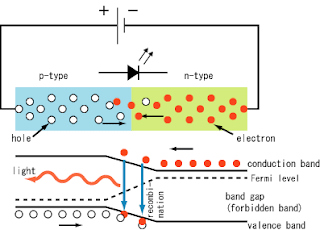
(Image is from: http://en.wikipedia.org/wiki/Light-emitting_diode)
The wavelength of the light emitted, and therefore its color, depends on the band gap energy of the materials forming the p-n junction.
Photodiodes
Photodiodes are one type of photo detectors (other types includes thermal detectors, photoresistors, photomultipliers, etc.).
Same as LED, a photodiode is a semiconductor p–n junction device. But opposite to LED, in a photodiode light is absorbed in a depletion region and generates a photocurrent. There are two operation modes for a photodiode:
Photovoltaic mode: operated in zero bias. The illuminated photodiode generates a voltage which can be measured. This is photovoltaic effect, which is the basis for solar cells—in fact, a solar cell is just an array of large area photodiodes.
Photoconductive mode: operated in reverse bias (opposite to LED). The resulting photocurrent can be measured. Detectors operated in this mode have high linearity and dynamic range.
References:
[1] http://en.wikipedia.org/wiki/Light-emitting_diode
[2] http://www.rp-photonics.com/photodiodes.html
LED physics: as shown in Fig. 1, current flows from the p-side (anode) to the n-side (cathode) when the diode is forward biased. When an electron meets a hole (electron-hole combination), it falls into a lower energy level, and releases energy in the form of a photon.

(Image is from: http://en.wikipedia.org/wiki/Light-emitting_diode)
The wavelength of the light emitted, and therefore its color, depends on the band gap energy of the materials forming the p-n junction.
Photodiodes
Photodiodes are one type of photo detectors (other types includes thermal detectors, photoresistors, photomultipliers, etc.).
Same as LED, a photodiode is a semiconductor p–n junction device. But opposite to LED, in a photodiode light is absorbed in a depletion region and generates a photocurrent. There are two operation modes for a photodiode:
Photovoltaic mode: operated in zero bias. The illuminated photodiode generates a voltage which can be measured. This is photovoltaic effect, which is the basis for solar cells—in fact, a solar cell is just an array of large area photodiodes.
Photoconductive mode: operated in reverse bias (opposite to LED). The resulting photocurrent can be measured. Detectors operated in this mode have high linearity and dynamic range.
| Material | Spectrum range |
|---|---|
| Silicon (Si) | 400-1000 nm |
| Germanium (Ge) | 900-1600 nm |
| Indium gallium arsenide phosphide (InGaAsP) | 1000-1350 nm |
| Indium gallium arsenide (InGaAs) | 900-1700 nm |
References:
[1] http://en.wikipedia.org/wiki/Light-emitting_diode
[2] http://www.rp-photonics.com/photodiodes.html
Subscribe to:
Posts (Atom)