Wednesday, August 12, 2009

Using Zemax as a calculator to calculate for Gaussian beam

Using Zemax to calculate for Gaussian beam propagation is handy and precise.

First set up your optical system in sequential mode. For example, a lens comprised of two surfaces. Here I have a diode window and a collimating lens:


Go to Analysis -> Physical Optics -> Paraxial Gaussian Beam, or simply Ctrl-B. A "Paraxial Gaussian Beam Data" window appears. Click Settings, or right click mouse, the setting menu appears.

Zemax asks for 4 initial values to define the input Gaussian beam:
(1)Wavelength: defined in "Wav" tab.
(2)Waist size: this is 1/e2 radius value. Note that this is for the embedded ideal Gaussian beam.Note 1
(3)M2 factor: the true Gaussian beam has Mx beam radius and Mx divergence compared to the embedded ideal Gaussian beam.
(4)Waist location.


After hitting OK, the "Paraxial Gaussian Beam Data" window gives Gaussian beam characteristics on all surfacesNote 2. Both embedded and true Gaussian modes will be given. This is better than calculating by hand or by Matlab code that I used to do.

What would be better: I wish Zemax can creat a drawing showing Gaussian beam's marginal ray.

Notes:
1. To convert your real beam's waist size to its embedded Gaussian beam's waist, divided it by M.
2. This is ideal paraxial result without considering any aberrations on the optics. To see how aberration changes the Gaussian beam size, use "Skew Gaussian Beam" function.

Wednesday, June 24, 2009

Abbe number and glass code


Abbe number:


V = nD - 1
nF-nC

(1)

where nD, nF and nC are the refractive indices of the material at the wavelengths of the Fraunhofer D-, F- and C- spectral lines (589.2 nm, 486.1 nm and 656.3 nm respectively). Low dispersion (low chromatic aberration) materials have high values of V [1].

Glass code:
Example of BK7:
517642
n = 1.517
V = 64.2
(both at 587.56 nm) [2]

References:
[1] http://en.wikipedia.org/wiki/Abbe_number
[2] http://en.wikipedia.org/wiki/Glass_code

ZEMAX un-organized tips

I have to do extensive ZEMAX work to start my semi-new job. Had some non-sequential mode experience but now I really have to use sequential mode, and optimization and tolerancing functions. The first two tasks are aspheric collimating lens for diode and fiber-coupling. Now let me start to accumulate the little rules/tips of ZEMAX:

1. When defining a sequential system, the first parameter to set is aperture. Some aperture types are:
a. Float by stop size: defined by the radius of the stop surface. This type of aperture is used when the stop surface is a real, unchangeable aperture buried in the system, for example, fiber coupling.
b. Object cone angle: defined by the half-angle in degrees of the marginal ray in object space. This can be used when designing a collimating lens for a diode laser.
(Ref[1], page 63)

2. Afocal system [2]. The strict definition of an afocal system is a system in which both object and image conjugates are at infinity. For example, a laser beam expander in which both input and output beams are collimated. In Zemax, as long as the image conjugate is at infinity, the system is afocal. For example, when designing a diode collimating lens, one will choose "Afocal image space" in Aperture settings:


3. Apodization type. This describes amplitude variation of the pupil illumination. Gaussian apodization is what a laserist often uses:


A(ρ) = exp(-2)

Here ρ is the normalized pupil coordinate, i.e., ρ = 0~1 from the center to the edge of the pupil. G is the apodization factor. If G = 1, the amplitude at the edge of the entrance pupil falls to 1/e of the center value (intensity falls to 1/e2). So the marginal ray represents the 1/e2 ray.
(Ref[1] page 64)

Marginal ray: is the ray that travels from the center of the object, to the edge of the entrance pupil, and onto the image plane.
(Ref[1] page 30)


References:
[1] ZEMAX user's guide Jan 2003
[2] Mark Nicholson, ZEMAX users' knowledge base - How to design afocal systems. http://www.zemax.com/kb/articles/36/1/How-to-Design-Afocal-Systems/Page1.html

Wednesday, May 6, 2009

LED and photodiode

LED

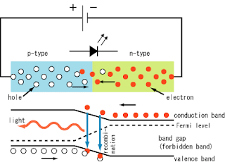
LED physics: as shown in Fig. 1, current flows from the p-side (anode) to the n-side (cathode) when the diode is forward biased. When an electron meets a hole (electron-hole combination), it falls into a lower energy level, and releases energy in the form of a photon.


(Image is from: http://en.wikipedia.org/wiki/Light-emitting_diode)

The wavelength of the light emitted, and therefore its color, depends on the band gap energy of the materials forming the p-n junction.

Photodiodes

Photodiodes are one type of photo detectors (other types includes thermal detectors, photoresistors, photomultipliers, etc.).

Same as LED, a photodiode is a semiconductor p–n junction device. But opposite to LED, in a photodiode light is absorbed in a depletion region and generates a photocurrent. There are two operation modes for a photodiode:

Photovoltaic mode: operated in zero bias. The illuminated photodiode generates a voltage which can be measured. This is photovoltaic effect, which is the basis for solar cells—in fact, a solar cell is just an array of large area photodiodes.

Photoconductive mode: operated in reverse bias (opposite to LED). The resulting photocurrent can be measured. Detectors operated in this mode have high linearity and dynamic range.


MaterialSpectrum range
Silicon (Si)400-1000 nm
Germanium (Ge)900-1600 nm
Indium gallium arsenide phosphide (InGaAsP)1000-1350 nm
Indium gallium arsenide (InGaAs)900-1700 nm


References:
[1] http://en.wikipedia.org/wiki/Light-emitting_diode
[2] http://www.rp-photonics.com/photodiodes.html

Thursday, April 30, 2009

Luminescence - photoluminescence - phosphorescence

Luminescence refers to light emission caused by electron transition from excited state to ground state; not by a rise in temperature (light emission from pure heat source is incandescence).

By different excitation(pumping) mechanism, luminescence has various types, for example:
  • Photoluminescence: material is pumped by absorption of photons (e.g., fluorescent lamp).

  • Cathodoluminescence: pumped by electron beam (e.g., CRT monitor).

  • Electroluminescence: pumped by electric current or field (e.g., LED).


Photoluminescence:
From the transition speed, photoluminescence is divided into two types:
  • Fluorescence: an almost instantaneous effect; the emission ends within ~10-8 second after excitation.

  • Phosphorescence: this term describes the persistent luminescence (afterglow) of phosphors (the "glow-in-the-dark" phenomenon). The upper state is either metastable with long lifetime or is transition forbidden to the ground state.


Phosphorescence:
Materials exihibiting phosphorescence are known as phosphors. Phosphors are usually some microcystalline materials. In these crystals, there are impurity ions called activators, which replaces some host ions in the crystal lattice. These activators form luminescing centers and are where the excitation-emission process occurs.

References
[1] John Wilson and John Hawkes, Optoelectronics, an introduction, 3rd ed., Prentice Hall Eruope, 1998. Chapter 4.
[2] Luminescence article at www.britannica.com
[3] Other sites that explain the phosphorescence physics:
http://math.ucr.edu/home/baez/spin/node17.html
http://en.wikipedia.org/wiki/Phosphorescence

Tuesday, April 28, 2009

Photometric meters

1. Goniophotometer [1]
The Greek word "gonio" means angle. A goniophotometer measures spatial distribution (xyz and angular) of a radiation source. It has a built-in photopic [2] filter so all measured radiometric quantities automatically convert to photometric ones after calibration. A goniophotometer is able to measure:

  • Luminous power (flux) in lm.

  • Luminous intensity in cd = lm/Sr.

  • Illuminance in lux = lm/m2.

  • Luminance in cd/m2 = lm/m2-Sr.

  • Color coordinates and correlated color temperature.

  • Sample's retro-reflection as function of angle in cd/lx.


2. Colorimeter [3]
There are also filters in a colorimeter to mimic the human cone response. A colorimeter produces numerical results in one of the CIE color models.

References and notes:
[1] X-Rite GmbH - Optronik catalog.
[2] The word "photopic" refers to vision by cone receptors in the human eye (while "scotopic" refers to rod receptors).
[3] Bruce Fraser, Chris Murphy, and Fred Bunting, Real World Color Management, 2nd ed. Peachpit Press 2005. Page 43.

Monday, April 27, 2009

Radiometry and photometry

Radiometry means the measurement of radiation. Photometry is a modified radiometry when wavelength is weighted by how sensitive the human eye responses.

Both radiometry and photometry have their own tricky/bizarre names for basic quantities:

1. Radiometry quantities:


NameOther nameUnitsSymbol
Energy
joule (J)Q
FluxRadiant powerwatt (W) Φ
IrradianceFlux DensityW/m2
Radiant exitance
W/m2M
Radiant incidance
W/m2E
Radiant intensityW/SrI
Radiance
W/(m2Sr)L


Descriptions:
Flux (radiant power): time rate of change of energy.
Irradiance: areal density of power. I noticed more and more scientific articles have used this term to replace "intensity", which is good.
Radiant intensity: power per unit solid angle.
Radiance: power per unit projected area per unit solid angle. (This is equivalent to brightness often used by laser people).

2. Photometry quantities:
Same as radiometric quantities but units have different names:


Radiometric namePhotometric nameRadiometric unitsPhotometric units
Energyjoule (J)
Radiant power (flux)Luminous power (flux)watt (W)lumen (lm)
IrradianceIlluminanceW/m2lm/m2 = lux (lx)
Radiant intensityLuminous intensityW/Srlm/sr = candela (cd)
RadianceLuminanceW/(m2Sr)lm/(m2Sr) = cd/m2 = nit


Descriptions:
Candela: (unit of luminous intensity) one of the seven base units of the SI system. If a monochromatic 555nm source emits 1 W per steradian at a given direction, then at that direction the luminous intensity is 683 candelas (or 683 lm/sr). 555 nm is the wavelength that human eye has the max spectral responsivity.
Lumen: (unit of luminous power) For an isotropic source having 1 candela luminous intensity, the total luminous power emitted is 4π. If a source is not isotropic, one needs to measure the luminous intensity in many directions using a goniophotometer, and then numerically integrate over the entire sphere.
Lux: (unit of illuminance) = lm/m2. Most light meter measures this quantity.

3. Conversion between Watt and Lumen
The simplest thing to remember is:
1 Watt = 683 Lumens @555 nm.
At other wavelengths, this value is smaller and we need to multiply the eye's spectral response curve V(λ).

References:
[1] There is an excellent article on this subject by late Professor James M. Palmer:
http://www.optics.arizona.edu/Palmer/rpfaq/rpfaq.pdf
[2] The book Introduction to Radiometry (SPIE Optical Engineering Press 1998) by William L. Wolfe is a full-range detailed reference. I found some slight differences between the two references on quantity naming. This means that this subject is still somehow not coordinated.

Thursday, April 23, 2009

Opponent colors

There exist three opponent color pairs:
Light-Dark;
Red-Green;
Yellow-Blue.

We cannot have something that is both light and dark, or red and green, or yellow and blue (but we can have reddish-yellow (orange) and blueish-red (purple), etc.). The two colors in each pair are totally opposite or exclusive. This fact enables us to establish LAB, a 3-D color space, in which these three pairs are the three axes.

Structure below shows the relationship. The diagonal colors are opponent pairs:

(O)
R - Y
(M) | |
B - G
(C)

(橙)
红--黄
(品红) | |
蓝--绿
(青)


It seems that there should be four basic or root colors (RYBG), however Y can be produced by mixing R and G (this makes sense as Y resides between R and G in spectrum, so the overall response from eye cone receptors is yellow) so Y is not a primary color.

Anyway, opponent colors are very mysterious to me.

Opponent colors appear in our afterimage or ghost image, which refers to an image continuing to appear in one's vision after the exposure to the original image has ceased [2].

Are opponent color pairs the same as the inverse colors in the negative film? I don't think so. The three primary colors in negative film should be CMY.


References:

1. Bruce Fraser, Chris Murphy, and Fred Bunting, Real World Color Management, 2nd ed. Peachpit Press 2005
2. www.absoluteastronomy.com/topics/Afterimage

Sunday, April 12, 2009

Brightness, hue, and saturation

These are the three attributes of color.

Brightness is the achromatic component, i.e., light power or intensity that detected by our eye.

Hue and saturation are the chromatic components. Simply defining,
Hue = wavelength;
Saturation = spectral purity.

Hue:
The wavelength that appears most prevalent in a color sample determines its hue. The set of basic hues, for example, 赤橙黄绿青蓝紫, is very subjective and differ from culture to culture.

Saturation:
"Spectral purity" is enough to define saturation. Lasers produce the most saturated colors whereas white-gray-black are the least saturated colors.

References:
1. Bruce Fraser, Chris Murphy, and Fred Bunting, Real World Color Management, 2nd ed. Peachpit Press 2005

Friday, April 10, 2009

Eye and color event

1. Eye structure:

(Image is from: http://www.schools.net.au/edu/lesson_ideas/optics/optics_wksht2_p1.html)

Of all these names I should know the most important ones as an optical scientist:

Cornea: focusing light to form an image (together with lens; but cornea plays the major role on focusing [1, page 16]).

Iris: aperture.

Lens: besides focusing adjustment, it also acts as a UV filter to protect the retina.

Retina: see next section.


2. Retina

There are two types of nerve cells, or receptors, in the retina:

Rods: provide vision at low light and has a peak absorption at 499nm. It is color blind.

Cones: provide color info. The three types of cones, RGB, have peak responses at 420nm, 530nm and 565nm respectively.

(Image is from: Eysenck, Cognitive Psychology: A Student's Handbook)

Therefore one can stimulate almost any colors by using just three well-chosen primary colors.

Additive primary colors - RGB:
starting from black (no wavelengths), adding R,G,B one by one, we obtain white light (all wavelengths).

Subtractive primary colors - CMYK:
starting from white,
subtracting cyan, we get red (cyan ink is "red-subtractor" or "long-wavelength subtractor");
subtracting magenta, we get green (magenta ink is "green-subtractor" or "medium-wavelength subtractor");
subtracting yellow, we get blue (yellow ink is "blue-subtractor" or "short-wavelength subtractor").

Opponent color pairs:
This is very mysteries to me. The opponent color pairs are:
Light-Dark;
Red-Green;
Yellow-Blue.

3. Color event

Strictly speaking, color is an event. It is a product of three things: light, object, and observer.

4. Metamerism

Metamerism is a phenomenon that two incident lights with different spectra produce the same color sensation by human eye. For example, a blend of R and G produces Y but this is different from a pure Y produced by a yellow laser, although both appear the same color, yellow, to our eye. Another example is that two clothes having the same color in store may become different colors viewed under sunlight or at home. This is because of the limitation of our eye as a spectrum analyzer. Our eye divides the incident light into only 3 components by the R,G,B receptors, whereas an optical spectrum analyzer is able to divide the incident light into many pieces. In other words, our eye's resolution bandwidth is very crude and this causes metamerism.

Metamerism is good! Why? Because if without metamerism, our printers would need many inks in all different colors, instead of just four (CMYK).

References:
1. Bruce Fraser, Chris Murphy, and Fred Bunting, Real World Color Management, 2nd ed. Peachpit Press 2005

Light source and color temperature

1. Hot source and cold source:

Light emission (I am talking about incoherent light, not laser light this time) is from two basic types of sources: heat source and non-heat (or cold) source. For the first source, light radiation is only from thermal energy and we call it blackbody radiator (this process is called incandescence). For the latter source, light is not caused by a rise in temperature and we call it luminescence process.

2. Color temperature:

This term is only for blackbody radiators. At 3200K, long wavelength dominates; light appears yellow and is from a typical incandescent light bulb. When temperature rises to 5000K, the blackbody emits relatively flat spectrum and is a very neutral white. At higher temperature, short wavelength starts to dominate and appears blueish.


Figure is from: www.techmind.org/colour/coltemp.html

So when we talk about color temperature, remember it is only for pure thermal source! But color temperature is used very often on all other sources, e.g., fluorescence light tubes. Strictly speaking, this should be called "correlated color temperature" because people are picking the closest blackbody temperature to quantize the color the source appears.

(In addition, color temperature is for white light. When we want to know or quantize how white a source is, we use color temperature so we know if it is neutral, blueish or yellowish. For monochromatic sources, color temperature is no use.)

3. Luminescence:

Luminescence is light that emitted at low temperatures without heat so it is "cold body radiation" (as compared to blackbody radiation). Fluorescence is only one mechanism of luminescence: the material absorb high-energy photons at UV or blue spectrum and re-emit photons (Stokes photon) in the visible spectrum. An example is UV brightener, a material that paper and ink manufacturers use to make an extra-white paper or extra-bright ink.

Atomic physics view of luminescence vs. incandescence:
Luminescence occurs when material absorbs external energy and electrons are pumped to excited states, then the radiative transition back to lower state produces luminescence emission. Incandescence emission is from the thermal vibration of heated atoms themselves. This temperature radiation is in the far IR spectrum region when material is at room temperature and shifts towards visible when material's temperature increases.

References:
1. Bruce Fraser, Chris Murphy, and Fred Bunting, Real World Color Management, 2nd ed. Peachpit Press 2005.
2. Luminescence (physics) -- Britannica Online Encyclopedia. www.britannica.com

Sunday, January 18, 2009

Gold-tin solder

Today's high-power electronic and optical devices require better heat transfer to the heat sink. Gold-tin (AuSn) solder is the answer to such packaging challenges. This is because AuSn solder has superior high-temperature performance, excellent electrical and thermal conductivity, high mechanical strength, and fluxless soldering [1].

Today I read from nLight's website [2] that they use AuSn soldering of high-power diode emitters onto the coefficient-of-thermal-expansion (CTE) matched heatsinks (such as BeO). Compared to the traditional indium soldering ("soft soldering") onto copper heatsink, the AuSn soldering ("hard soldering") has significantly increased reliability.

References:
[1] http://www.flipchips.com/tutorial46.html
[2] http://nlight.net/nlight-files/file/technical_papers/LEOS2008-AnnualMeeting_Leisher.pdf

Thursday, January 15, 2009

About VCSEL

VCSEL: Vertical Cavity Surface Emitting Laser.

VCSEL's laser resonator consists of two distributed Bragg reflector (DBR) mirrors with high reflectance >99%. This high reflectance is required to compensate for the short axial length of the gain region.

Advantages (compared to edge-emitters, of course):
1. Laser cavity is short (1~1.5 λ), so only one longitudinal mode can oscillate. (The longitudinal mode spacing is λ/2).
2. The high reflective resonator mirrors results in low threshold current so VCSEL has lower power consumption. (However lower output optical power.)
3. λ vs. T (<0.1 nm/K) is ~5 times smaller than edge emitters (0.2~0.3 nm/K).
4. Easier thermal dissipation and high T operation.
5. Circular output beam. This brings easier beam shaping, easier fiber-coupling, etc.
6. High reliability. VCSEL is not subject to catastrophic optical damage (COD).
7. When put in external-cavity, EC-VCSEL has no mode-hops during tuning or modulation because of the large mode-spacing.

Disadvantages:
Need to do more search on this.
The brightness of the high-power VCSEL is still lower than edge-emitters (why?)

References:
[1] Princeton Optronix website.
[2] http://en.wikipedia.org/wiki/VCSEL

Wednesday, January 14, 2009

About Fiber

I need to go over some basic knowledge on fibers.

1. V number.
The number of modes in a step index circular waveguide is determined by the V number.


V = 2πaNA
λ0

(1)

For single-mode fiber, V < 2.405. For multi-mode fiber the number of modes allowed in the fiber is approximately V2/2.

2. Numerical aperture.
The sine of the half acceptance angle is NA.
NA = (ncore2 - nclad2)1/2.
For reference,
f# = 1/(2 NA).
Note that it is not necessarily true that a fiber's output beam's divergence angle will equal to its acceptance angle. Instead, the fiber tends to preserve the angle of incidence during propagation of the light, causing it to exit the fiber at the same angle it entered.

References:
1. http://www.fiberoptix.com/technical/numerical-aperature.html
2. Wilson and Hawkes, Optoelectronics, 3rd ed., Prentice Hall Europe 1998.

Monday, January 12, 2009

Second Harmonic Generation

A few issues here:

1. How to explain or understand phase-matching easily.
Well, there is dispersion in all materials. For fundamental and 2nd harmonic waves, different wavelength causes different refractive index and then causes different traveling velocity. Consequently, along the propagation direction, the previously-generated 2nd-harmonic-wave and the newly-generated 2nd-harmonic-wave will have different phase. Thus destructive interference will happen and this is phase-mismatching. To fulfill phase-matching, we use birefringence property of some crystals. At certain direction, the cross-polarized fundamental and 2nd-harmonic waves can have the same traveling speed.

2. Type-I and type-II phase-matching.
Type-I: the signal and idler beams have the same polarization. In SHG, signal and idler are equal, which are both the fundamental beam. So in SHG, type-I phase-matching is for polarized fundamental laser.
Type-II: the signal and idler beams have perpendicular polarization. In SHG, type-II phase-matching is for unpolarized fundamental laser.

3. Impedance matched cavity.
For cavity-enhanced SHG, we want the transmission of the input mirror at the pump wavelength equals all intracavity pump losses, including the loss from nonlinear frequency conversion. This way the initial pump reflection and the cavity leakage field will cancel (they always have opposite phase), resulting in zero total pump reflection. Thus all pump light will be coupled into cavity and maximize the conversion efficiency.

4. Major drawback of the intracavity SHG.
It is called "green noise", the intensity instability caused by interaction of multiple longitudinal modes of the fundamental laser.

Friday, January 9, 2009

About Fiber Laser

Fiber lasers generally use fiber Bragg grating to form the laser cavity.

Advantages:
1. Fiber lasers can produce high power light at excellence beam quality.
2. Fiber lasers use rare-earth doped glass fibers, which has larger gain bandwidth compared with the rare-earth doped bulk crystals. Fiber lasers thus can have broad tuning range and can generate short pulses via mode-locking.
3. Fiber lasers have large surface-to-volume ratio and are easier for thermal management.
4. Fiber lasers are very mechanically stable against vibrations.

Difficulties:
1. Efficiently coupling pump diodes into the fiber has tight alignment tolerance.
2. Fibers have birefringence and polarization control is difficult.

Fiber lasers use double-clad fiber. The gain medium is in the center core, where the lasing mode propagates; whereas the inner cladding layer contains the pump light.

To generate single-mode laser beam at high power, and to decrease nonlinearity, etc, "large mode area single-mode fiber" is now used for fiber laser [2]. Since it has large mode area, to ensure single-mode propagation, the fiber must have a low NA (keep V-number low). For example, a Yb-doped fiber laser has a 20um core (NA=0.06) and a 400um clad (NA=0.46).

Fiber lasers often are broad-band lasing to eliminate Brillouin scattering.

References:
[1] http://en.wikipedia.org/wiki/Fiber_laser
[2] http://www.nufern.com/whitepaper_detail.php/30