
The prism positions are designed for 488nm, wavelengths deviating from 488nm will have some beam walk-off (both displacement and steering). Now I want to know how much I need to twist the prism pair for correcting the beam walk-off. The pivot point of twisting is a pin at somewhere not far from the prisms. (Twist the two prisms together since this is a sub-assembly).
To simulate it in Zemax, I first draw the prisms in SolidWorks with the pivot pin:
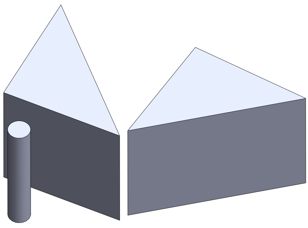
Note that in SolidWorks I make the origin point at the pin location. Then I Save As the model in IGS format, to folder C:\Program Files\ZEMAX\Objects\CAD Files. After Zemax imports this file, the reference point is at the pin, which is what I wanted. I found that saving as STL file won't keep the reference point at the same location as in SolidWorks.
Below is the Zemax screen capture. It is a non-sequential model. I can rotate two prisms together around the pin location in Zemax. Beam compression, displacement and steering can all be checked. (Click on images to see in full size.)


No comments:
Post a Comment